
图书条目标准图
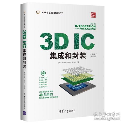
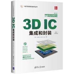
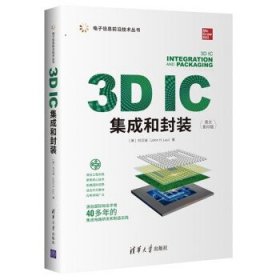
3D IC集成和封装
¥ 161 全新
仅1件
安徽合肥
认证卖家担保交易快速发货售后保障
作者[美]刘汉诚(John H. Lau)
出版社清华大学出版社
出版时间2022-04
版次1
装帧其他
货号gyfs
上书时间2024-04-16


商品详情
- 品相描述:全新
图书标准信息
- 作者 [美]刘汉诚(John H. Lau)
- 出版社 清华大学出版社
- 出版时间 2022-04
- 版次 1
- ISBN 9787302600657
- 定价 129.00元
- 装帧 其他
- 开本 16开
- 纸张 胶版纸
- 【内容简介】
- 本书系统介绍用于电子、光电子和MEMS器件的2.5D、3D以及3D IC集成和封装技术的前沿进展和演变趋势,讨论3D IC集成和封装关键技术的主要工艺问题和解决方案。主要内容包括半导体工业中的集成电路发展,摩尔定律的起源和演变历史,三维集成和封装的优势和挑战,TSV制程与模型、晶圆减薄与薄晶圆在封装组装过程中的拿持晶圆键合技术、三维堆叠的微凸点制作与组装技术、3D硅集成、2.5D/3D IC和无源转接板的3D IC集成、三维器件集成的热管理技术、封装基板技术,以及存储器、LED、MEMS、CIS 3D IC集成等关键技术问题,最后讨论PoP、Fanin WLP、eWLP、ePLP等技术。本书主要读者对象为微电子领域的研究生和从事相关领域的科学研究和工程技术人员。
- 【作者简介】
-
刘汉诚(John H. Lau),伊利诺伊大学香槟分校理论与应用力学博士,不列颠哥伦比亚大学结构工程硕士,威斯康星大学麦迪逊分校工程力学硕士,菲尔莱狄更斯大学管理科学硕士,台湾大学土木工程学士。
历任台湾欣兴电子股份有限公司CTO、香港ASM太平洋科技有限公司高级技术顾问、台湾工业技术研究院研究员、香港科技大学客座教授、新加坡微电子研究院MMC实验室主任、惠普实验室/安捷伦公司资深科学家(超过25年)。
拥有40多年的集成电路研发和制造经验,专业领域包括集成电路的设计、分析、材料、工艺、制造、认证、可靠性、测试和热管理等,目前研究领域为芯片异构集成、SiP、TSV、扇出/扇入晶圆/面板级封装、MEMS、mini/ micro LED、3D IC集成、SMT和焊接力学等。
发表480多篇论文,发明30多项专利,举办 300多场讲座,撰写20多部教科书(涉及3D IC 集成、TSV、先进 MEMS 封装、倒装芯片 WLP、面积阵列封装、高密度 PCB、SMT、DCA、无铅材料、焊接、制造和可靠性等领域)。
ASME Fellow、IEEE life Fellow、IMAPS Fellow,积极参与ASME、IEEE和IMAPS的多项技术活动。获得ASME、IEEE、SME等协会颁发的多项荣誉,包括IEEE/ECTC最佳会议论文(1989)、IEEE/EPTC最佳论文奖(2009)、ASME Transactions最佳论文奖(电子封装杂志,2000)、IEEE Transactions最佳论文奖(CPMT,2010)、ASME/EEP杰出技术成就奖(1998)、IEEE/CPMT电子制造技术奖(1994)、IEEE/CPMT杰出技术成就奖(2000)、IEEE/CPMT杰出持续技术贡献奖(2010)、SME电子制造全面卓越奖(2001)、潘文渊杰出研究奖(2011)、IEEE 继续教育杰出成就奖(2000)、IEEE CPMT技术领域奖(2013)和 ASME 伍斯特·里德·华纳奖章(2015)等。 - 【目录】
-
1 3D Integration for Semiconductor IC Packaging
1.1 Introduction
1.2 3D Integration
1.3 3D IC Packaging
1.4 3D Si Integration
1.5 3D IC Integration
1.5.1 Hybrid Memory Cube
1.5.2 Wide I/O DRAM and Wide I/O 2
1.5.3 High Bandwidth Memory
1.5.4 Wide I/O Memory (or Logic-on-Logic)
1.5.5 Passive Interposer (2.5D IC Integration)
1.6 Supply Chains before the TSV Era
1.6.1 FEOL (Front-End-of-Line)
1.6.2 BEOL (Back-End-of-Line)
1.6.3 OSAT (Outsourced Semiconductor Assembly and Test)
1.7 Supply Chains for the TSV Era—Who Makes the TSV?
1.7.1 TSVs Fabricated by the Via-First Process
1.7.2 TSVs Fabricated by the Via-Middle Process
1.7.3 TSVs Fabricated by the Via-Last (from the Front Side) Process
1.7.4 TSVs Fabricated by the Via-Last (from the Back Side) Process
1.7.5 How About the Passive TSV Interposers?
1.7.6 Who Wants to Fabricate the TSV for Passive Interposers?
1.7.7 Summary and Recommendations
1.8 Supply Chains for the TSV Era—Who Does the MEOL,Assembly, and Test?
1.8.1 Wide I/O Memory (Face-to-Back) by TSV Via-Middle Fabrication Process
1.8.2 Wide I/O Memory (Face-to-Face) by TSV Via-Middle Fabrication Process
1.8.3 Wide I/O DRAM by TSV Via-Middle Fabrication Process
1.8.4 2.5D IC Integration with TSV/RDL Passive Interposers
1.8.5 Summary and Recommendations
1.9 CMOS Images Sensors with TSVs
1.9.1 Toshiba’s Dynastron TM
1.9.2 STMicroelectronics’ VGA CIS Camera Module
1.9.3 Samsung’s S5K4E5YX BSI CIS
1.9.4 Toshiba’s HEW4 BSI TCM5103PL
1.9.5 Nemotek’s CIS
1.9.6 SONY’s ISX014 Stacked Camera Sensor
1.10 MEMS with TSVs
1.10.1 STMicroelectronics’ MEMS Inertial Sensors
1.10.2 Discera’s MEME Resonator
1.10.3 Avago’s FBAR MEMS Filter
1.11 References
2 Through-Silicon Vias Modeling and Testing
2.1 Introduction
2.2 Electrical Modeling of TSVs
2.2.1 Analytic Model and Equations for a Generic TSV Structure
2.2.2 Verification of the Proposed TSV Model in Frequency Domain
2.2.3 Verification of the Proposed TSV Model in Time Domain
2.2.4 TSV Electrical Design Guideline
2.2.5 Summary and Recommendations
2.3 Thermal Modeling of TSVs
2.3.1 Cu-Filled TSV Equivalent Thermal Conductivity Extraction
2.3.2 Thermal Behavior of a TSV Cell
2.3.3 Cu-Filled TSV Equivalent Thermal Conductivity Equations
2.3.4 Verification of the TSV Equivalent Thermal Conductivity Equations
2.3.5 Summary and Recommendations
2.4 Mechanical Modeling and Testing of TSVs
2.4.1 TEM between the Cu-Filled TSV and Its Surrounding Si
2.4.2 Experimental Results on Cu Pumping during Manufacturing
2.4.3 Cu Pumping under Thermal Shock Cycling
2.4.4 Keep-Out-Zone of Cu-Filled TSVs
2.4.5 Summary and Recommendations
2.5 References
3 Stress Sensors for Thin-Wafer Handling and Strength Measurement
3.1 Introduction
3.2 Design and Fabrication of Piezoresistive Stress Sensors
3.2.1 Design of Piezoresistive Stress Sensors
3.2.2 Fabrication of the Stress Sensors
3.2.3 Summary and Recommendations
3.3 Application of Stress Sensors in Thin-Wafer Handling
3.3.1 Design, Fabrication, and Calibration of Piezoresistive Stress Sensors
3.3.2 Stress Measurement in Wafer after Thinning
3.3.3 Summary and Recommendations
3.4 Application of Stress Sensors in Wafer Bumping
3.4.1 Stresses after UBM Fabrication
3.4.2 Stresses after Dry-Film Process
3.4.3 Stresses after Solder Bumping Process
3.4.4 Summary and Recommendations
3.5 Application of Stress Sensors in Drop Test of Embedded Ultrathin Chips
3.5.1 Test Vehicle and Fabrication
3.5.2 Experimental Setup and Procedure
3.5.3 In-Situ Stress Measurement Results
3.5.4 Reliability Testing
3.5.5 Summary and Recommendations
3.6 References
4 Package Substrate Technologies
4.1 Introduction
4.2 Package Substrate with Build-up Layers for Flip Chip 3D IC Integration
4.2.1 Surface Laminate Circuit Technology
4.2.2 The Trend in Package Substrate with Build-up Layers
4.2.3 Summary and Recommendations
4.3 Coreless Package Substrates
4.3.1 Advantages and Disadvantages of Coreless Package Substrates
4.3.2 Substitution of Si Interposer by Coreless Substrates
4.3.3 Warpage Problem and Solution of Coreless Substrates
4.3.4 Summary and Recommendations
4.4 Recent Advance of Package Substrate with Build-up Layer
4.4.1 Thin-Film Layers on Top of Build-up Layer of Package Substrate
4.4.2 Warpage and Qualification Results
4.4.3 Summary and Recommendations 4.5 References
5 Microbumps: Fabrication, Assembly, and Reliability
5.1 Introduction
5.2 Fabrication, Assembly, and Reliability of 25-μm-Pitch Microbumps
5.2.1 Test Vehicle
5.2.2 Structure of the Microbumps
5.2.3 Structure of the ENIG Pads
5.2.4 Fabrication of the 25-μm-Pitch Microbumps
5.2.5 Fabrication of ENIG Bonding Pads on Si Carrier
5.2.6 Thermal Compression Bonding Assembly
5.2.7 Evaluation of the Underfill
5.2.8 Reliability Assessment
5.2.9 Summary and Recommendations
5.3 Fabrication, Assembly, and Reliability of 20-μm-Pitch Microbumps
5.3.1 Test Vehicle
5.3.2 Assembly of Test Vehicle
5.3.3 Formation of Microjoints by Thermocompression Bonding
5.3.4 Microgap Filling
5.3.5 Reliability Test
5.3.6 Reliability Test Results and Discussion
5.3.7 Failure Mechanism of the Microjoints
5.3.8 Summary and Recommendations
5.4 Fabrication, Assembly, and Reliability of 15-μm-Pitch Microbumps
5.4.1 Microbumps and UBM Pads of the Test Vehicle
5.4.2 Assembly
5.4.3 Assembly with CuSn Solder Microbump and ENIG Pad
5.4.4 Assembly with CuSn Solder Microbump and CuSn Solder Microbump
5.4.5 Evaluation of Underfill
5.4.6 Summary and Recommendations
5.5 References
6 3D Si Integration
6.1 Introduction
6.2 The Electronic Industry
6.3 Moore’s Law and More-Than-Moore
6.4 The Origin of 3D Integration
6.5 Overview and Outlook of 3D Si Integration
6.5.1 Bonding Methods for 3D Si Integration
6.5.2 Cu-to-Cu (W2W) Bonding
6.5.3 Cu-to-Cu (W2W) Bonding with Post-Annealing
6.5.4 Cu-to-Cu (W2W) Bonding at Room Temperature
6.5.5 SiO 2 -to-SiO 2 (W2W) Bonding
6.5.6 A Few Notes on W2W Bonding
6.6 3D Si Integration Technology Challenges
6.7 3D Si Integration EDA Challenges
6.8 Summary and Recommendations
6.9 References
7 2.5D/3D IC Integration
7.1 Introduction
7.2 TSV Process for 3D IC Integration
7.2.1 Tiny Vias on a Chip
7.2.2 Via-First Process
7.2.3 Via-Middle Process
7.2.4 Via-Last from the Front-Side Process
7.2.5 Via-Last from the Back-Side Process
7.2.6 Summary and Recommendations
7.3 The Potential Application of 3D IC Integration
7.4 Memory-Chip Stacking
7.4.1 The Chips
7.4.2 The Potential Products
7.4.3 Assembly Process
7.5 Wide I/O Memory or Logic-on-Logic
7.5.1 The Chips
7.5.2 The Potential Products
7.5.3 Assembly Process
7.6 Wide I/O DRAM or Hybrid Memory Cube
7.6.1 The Chips
7.6.2 The Potential Products
7.6.3 Assembly Process
7.7 Wide I/O 2 and High Bandwidth Memory
7.8 Wide I/O Interface (2.5D IC Integration)
7.8.1 Real Applications of TSV/RDL Passive Interposers
7.8.2 Fabrication of Interposers
7.8.3 Fabrication of TSVs
7.8.4 Fabrication of RDLs
7.8.5 Fabrication of RDLs—Polymer/Cu-Plating Method
7.8.6 Fabrication of RDLs—Cu Damascene Method
7.8.7 A Note on Contact Aligner for Cu Damascene Method
7.8.8 Back-Side Processing and Assembly
7.8.9 Summary and Recommendations
7.9 Thin-Wafer Handling
7.9.1 Conventional Thin-Wafer Handling Method
7.9.2 TI’s TSV-WCSP Integration Process
7.9.3 TSMC’s Thin-Wafer Handling with Polymer
7.9.4 TSMC’s Thin-Wafer Handling without Temporary Bonding and De-Bonding
7.9.5 Thin-Wafer Handling with a Heat-Spreader Wafer
7.9.6 Summary and Recommendations
7.10 References
8 3D IC Integration with Passive Interposer
8.1 Introduction
8.2 3D IC Integration with TSV/RDL Interposer
8.3 TSV/RDL Interposer with Double-Sided Chip Attachments
8.3.1 The Structure
8.3.2 Thermal Analysis—Boundary Conditions
8.3.3 Thermal Analysis—TSV Equivalent Model
8.3.4 Thermal Analysis—Solder Bump/Underfill Equivalent Model
8.3.5 Thermal Analysis—Results
8.3.6 Thermomechanical Analysis—Boundary Conditions
8.3.7 Thermomechanical Analysis—Material Properties
8.3.8 Thermomechanical Analysis—Results
8.3.9 Fabrication of the TSV
8.3.10 Fabrication of the Interposer with Top-Side RDLs
8.3.11 TSV Reveal of the Cu-Filled Interposer with Top-Side RDLs
8.3.12 Fabrication of the Interposer with Bottom-Side RDLs
8.3.13 Passive Electrical Characterization of the Interposer
8.3.14 Final Assembly
8.3.15 Summary and Recommendations
8.4 TSV Interposer with Chips on Both Sides
8.4.1 The Structure
8.4.2 Thermal Analysis—Material Properties
8.4.3 Thermal Analysis—Boundary Conditions
8.4.4 Thermal Analysis—Result and Discussions
8.4.5 Thermomechanical Analysis—Material Properties
8.4.6 Thermomechanical Analysis—Boundary Conditions
8.4.7 Thermomechanical Analysis—Results and Discussions
8.4.8 Interposer Fabrication
8.4.9 Microbump Wafer Bumping
8.4.10 Final Assembly
8.4.11 Summary and Recommendations
8.5 Low-Cost TSH Interposer for 3D IC Integration
8.5.1 The New Design
8.5.2 Electrical Simulation
8.5.3 Test Vehicle
8.5.4 Top Chip with UBM/Pad and Cu Pillar
8.5.5 Bottom Chip with UBM/Pad/Solder
8.5.6 TSH Interposer Fabrication
8.5.7 Final Assembly
8.5.8 Reliability Assessments
8.5.9 Summary and Recommendations
8.6 References
9 Thermal Management of 2.5D/3D IC Integration
9.1 Introduction
9.2 Design Philosophy
9.3 The New Design
9.4 Equivalent Model for Thermal Analysis
9.5 Interposer with Chip/Heat Spreader on Its Top Side and Chip on Its Bottom Side
9.5.1 The Structure
9.5.2 Material Properties
9.5.3 Boundary Conditions
9.5.4 Simulation Results
9.6 Interposer with Chip/Heat Spreader on Its Top Side and Chip/Heat Slug on Its Bottom Side
9.6.1 The Structure and Boundary Conditions
9.6.2 Simulation Results
9.7 Interposer with Four Chips on Its Top Side with Heat Spreader
9.7.1 The Structure
9.7.2 Boundary Conditions
9.7.3 Simulation Results
9.7.4 Summary and Recommendations
9.8 Thermal Performance between 2.5D and 3D IC Integrations
9.8.1 The Structures
9.8.2 The Finite Element Models
9.8.3 Material Properties and Boundary Conditions
9.8.4 Simulation Results—Low-Power Applications
9.8.5 Simulation Results—High-Power Applications
9.8.6 Summary and Recommendations
9.9 Thermal Management System with TSV Interposers with Embedded Microchannels
9.9.1 The Structure
9.9.2 Adaptor
9.9.3 Heat Exchanger
9.9.4 Carriers
9.9.5 System Integration
9.9.6 Theoretical Analysis of the Pressure Drop
9.9.7 Experimental Process
9.9.8 Results and Discussions
9.9.9 Summary and Recommendations
9.10 References
10 Embedded 3D Hybrid Integration
10.1 Introduction
10.2 Trends of Optoelectronic Products
10.3 The Old Design—High-Frequency Data Link on PCB Using Optical Waveguides
10.3.1 Polymer Optical Waveguide
10.3.2 Simulations—Optical Coupling Models
10.3.3 Simulations—System Link Design
10.3.4 Assembly of the OECB
10.3.5 Measurement Results of the OECB
10.3.6 Summary and Recommendations
10.4 The Old Design—Embedded Board-Level Optical Interconnects
10.4.1 Fabrication of Polymer Waveguide
10.4.2 Fabrication of the 45° Micro-Mirror
10.4.3 Assembly Process of the OECB
10.4.4 Fabrication Process of Vertical-Optical Channel
10.4.5 Final Assembly
10.4.6 Summary and Recommendations
10.5 The New Designs
10.6 An Embedded 3D Hybrid Integration Design Example
10.6.1 Optical Design, Analysis, and Results
10.6.2 Thermal Design, Analysis, and Results
10.6.3 Mechanical Design, Analysis, and Results
10.6.4 Summary and Recommendations
10.7 Semi-Embedded TSV Interposer with Stress Relief Gap
10.7.1 Design Philosophy
10.7.2 Problem Definition
10.7.3 Semi-Embedded TSV Interposer Subjected to Operating Condition
10.7.4 Semi-Embedded TSV Interposer Subjected to an Environmental Condition
10.7.5 Summary and Recommendations
10.8 References
11 3D LED and IC Integration
11.1 Introduction
11.2 Status and Outlook of Haitz’s Law
11.3 LED Has Come a Long Way!
11.4 Four Key Segments of LED Products
11.4.1 Substrates for LED Epitaxial Deposition
11.4.2 LED Device Fabrication
11.4.3 Packaging Assembly and Test of LED
11.4.4 LED Final Product Assembly
11.4.5 Outlook of LED Products
11.5 3D LED and IC Integration
11.5.1 HP FCLED and Thin-Film FCLED
11.5.2 3D LED and IC Integration Packages
11.5.3 Manufacturing Process of 3D LED and IC Integration
11.5.4 Summary and Recommendations
11.6 2.5D IC and LED Integration
11.6.1 LED Packaging Using Si-Substrate with Cavities and Cu-Filled TSVs
11.6.2 Si-Substrate with Cavity and TSVs for LED Packaging
11.6.3 LED Wafer-Level Packaging
11.6.4 Summary and Recommendation
11.7 Thermal Management of 3D LED and IC Integration
11.7.1 The New Designs
11.7.2 3D IC and LED Integration: A Design Example
11.7.3 Boundary-Value Problem
11.7.4 Simulation Results (Channel Height = 700 μm)
11.7.5 Simulation Results (Channel Height = 350 μm)
11.7.6 Summary and Recommendations
11.8 References
12 3D MEMS and IC Integration
12.1 Introduction
12.2 MEMS Packaging
12.3 Design of 3D MEMS and IC Integration
12.3.1 3D MEMS and IC Integration with Lateral Electrical Feed-Through
12.3.2 3D MEMS and IC Integration with Vertical Electrical Feed-Through in ASIC
12.3.3 3D MEMS and IC Integration with Vertical Electrical Feed-Through in the Package Cap
12.3.4 3D MEMS and IC Integration with MEMS on ASIC with TSVs
12.3.5 2.5D/2.25D MEMS and IC Integration
12.4 Assembly Process of 3D MEMS and IC Integration
12.4.1 3D MEMS and IC Integration with Lateral Electrical Feed-Through
12.4.2 3D MEMS and IC Integration with Vertical Electrical Feed-Through in ASIC
12.4.3 3D MEMS and IC Integration with Vertical Electrical Feed-Through in Package Cap
12.4.4 A Note on Case 10—A Real 3D MEMS and IC Integration
12.4.5 Summary and Recommendations
12.5 Low-Temperature Bonding of 3D MEMS Packaging with Solders
12.5.1 3D IC and MEMS Integration with Different Chip Sizes
12.5.2 Cavity and TSVs in Cap Wafer
12.5.3 MEMS Chip to ASIC Wafer (C2W) Bonding
12.5.4 ASIC Wafer with MEMS Chips to Cap Wafer (W2W) Bonding
12.5.5 Summary and Recommendations
12.6 Recent Developments in Advanced MEMS Packaging
12.6.1 TSVs for Wafer-Level Packaging of RF MEMS Devices
12.6.2 Zero-Level Packaging for RF-MEMS Implementing TSVs and Metal Bonding
12.6.3 MEMS Package Based on Si-Interposer Wafer with Cu-Filled TSVs
12.6.4 Wafer-Scale Packaging for FBAR-Based Oscillators
12.6.5 Summary and Recommendations
12.7 References
13 3D CMOS Image Sensor and IC Integration
13.1 Introduction
13.2 FI-CIS and BI-CIS
13.3 3D CIS and IC Stacking
13.3.1 The Structure
13.3.2 Fabrication of the CIS Pixel Wafer and Logic IC Wafer
13.4 3D CIS and IC Integration
13.4.1 The Structure
13.4.2 Fabrication Process Flow of the Coprocessor Wafer
13.4.3 Fabrication Process Flow of the CIS Wafer
13.4.4 Final Assembly
13.5 Summary and Recommendations
13.6 References
14 3D IC Packaging
14.1 Introduction
14.2 Chip Stacking by Wirebonding
14.2.1 Au Wire
14.2.2 Cu Wire and Ag Wire
14.3 Package-on-Package (PoP)
14.3.1 Wirebonding PoP
14.3.2 Flip Chip PoP
14.3.3 Wirebonding Package on Flip Chip Package
14.3.4 PoP in iPhone 5s
14.4 Wafer-Level Packaging
14.4.1 Fan-In WLP
14.4.2 3D Chip-to-Chip WLP
14.5 Fan-Out eWLP
14.5.1 Fan-Out eWLP
14.5.2 3D eWLP—Two-Chip Stacking
14.5.3 3D eWLP—Chip on eWLP (Face-to-Face)
14.5.4 3D eWLP—Chip on eWLP (Face-to-Back)
14.5.5 3D eWLP—Package on eWLP
14.5.6 3D eWLP—eWLP on eWLP
14.6 Embedded Panel-Level Packaging
14.6.1 Advantages and Disadvantages
14.6.2 Various Chip-Embedding Processes
14.6.3 Embedded Chip in SiP Rigid Substrate
14.6.4 3D Embedded Chip in SiP Flexible Substrate
14.6.5 3D Embedded Stacking Chips in SiP Flexible Substrate
14.7 Summary and Recommendations
14.8 References
Index
点击展开
点击收起

相关推荐
— 没有更多了 —
以下为对购买帮助不大的评价